Silicone DFM Review Service
Define, Shape, and Validate Your Product.
- From Idea to Mold-Ready Design
- DFM Review Before Any Tooling Begins
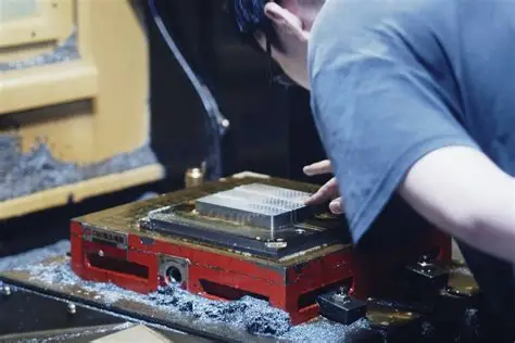
- Manufacturing Limits Identified Before Aluminum Is Cut
"We can't solve what we don't define."
You bring the design. The tooling is ours. Before any aluminum is cut, we review your design against how a mold actually works around it, geometry, material behavior, and process constraints across compression molding, LSR injection, and overmolding.
- Design reviewed against real mold mechanics
- Material and durometer confirmed for the process
- Manufacturing limits identified before tooling begins
- Alternatives proposed when a design needs adjustment
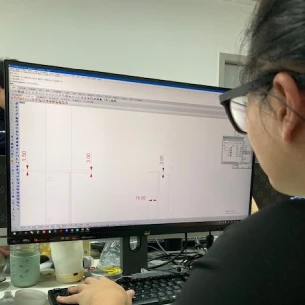
How Our Design & Engineering Process Works
From first idea to mold-ready CAD, our process runs through two phases: Phase I: Design Discovery when no CAD file exists, and Phase II: Design Validation when a CAD model is ready for pre-tooling review.
Phase I: Design Discovery
When your idea exists as a sketch, a sample, or a description, we start by defining the real geometry, not rough dimensions.
- Capture intent from sketches, samples, or photos.
- Define the envelope your part must fit within.
- Map functional zones: sealing, flexing, load points.
- Build an engineering view before tooling is discussed.
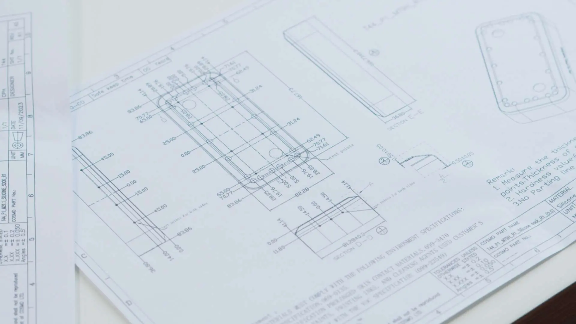
Why Flat Dimensions Mislead
Saying a part "fits in 100 mm × 80 mm × 20 mm" describes volume, not shape. Silicone design depends on curves, angles, and surfaces.
- Wall angles and slopes affect draft and pull risk.
- Flat vs. curved mating surfaces change parting line options.
- Contours to faces, pipes, or housings must be defined early.
- How the part compresses and flexes determines wall thickness.
Geometry Validation Process
Step 1 – Question geometry first
- Clarify functional constraints and use cases.
- Identify risk areas for sealing, pull-out, or tearing.
Step 2 – Build a working geometry envelope
- Physical sample: 3D scanning to create a reference shell.
- Photos / sketches: Virtual envelope with curvature refinement.
- Result: A validated design envelope where the part can exist and how it must fit.
Phase II: Design Validation (CAD File Exists)
With a CAD model, you are at the pre-tooling engineering stage. We run a 12-point DFM review so your design is ready for tooling and scaling.
- Geometry & DFM fundamentals: walls, draft, undercuts.
- Parting line, gating, flow paths, vents, and deflashing.
- Tolerance and shrinkage control for LSR or HCR silicone.
- Material, durometer, and surface finish confirmation.
- Tooling strategy, cavity count, and cycle-time efficiency.
- Regulatory fit for medical, food, or automotive requirements.
Problems We Catch Before Tooling Begins
Your design is correct for function. These problems only appear when someone thinks about how a mold works around that design.
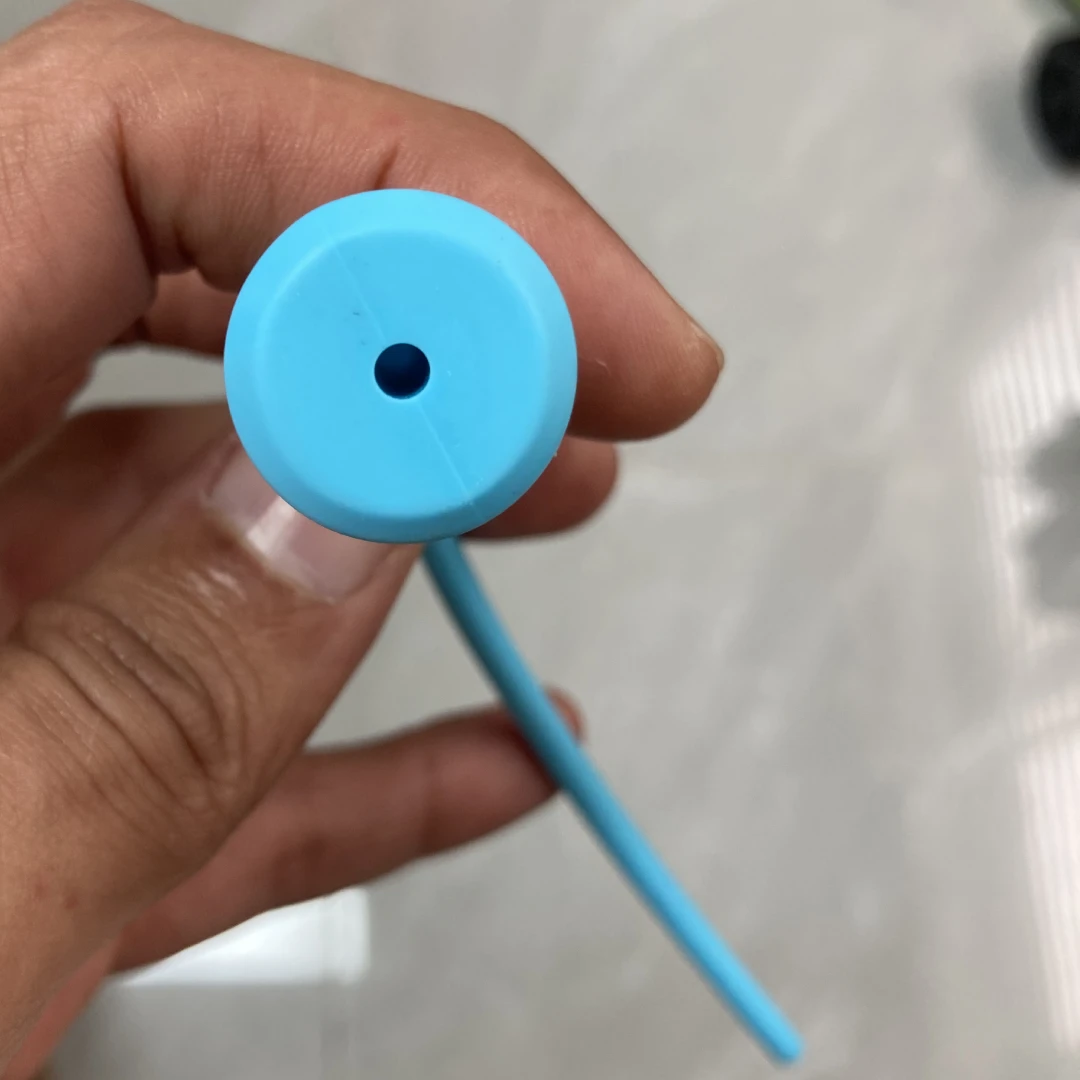
Blind Hole That Would Never Center
COMPRESSION MOLDING / CORE PIN
A silicone pin with a blind hole running most of its length. Correctly designed for function. A core pin with no through-support deflects under compression molding pressure. The hole comes out off-center on every part.
What we did
Extended the core pin through the full length. The remaining 2 mm at the tip was closed in a second shot. The finished part has a centered hole. Your design intent was preserved.
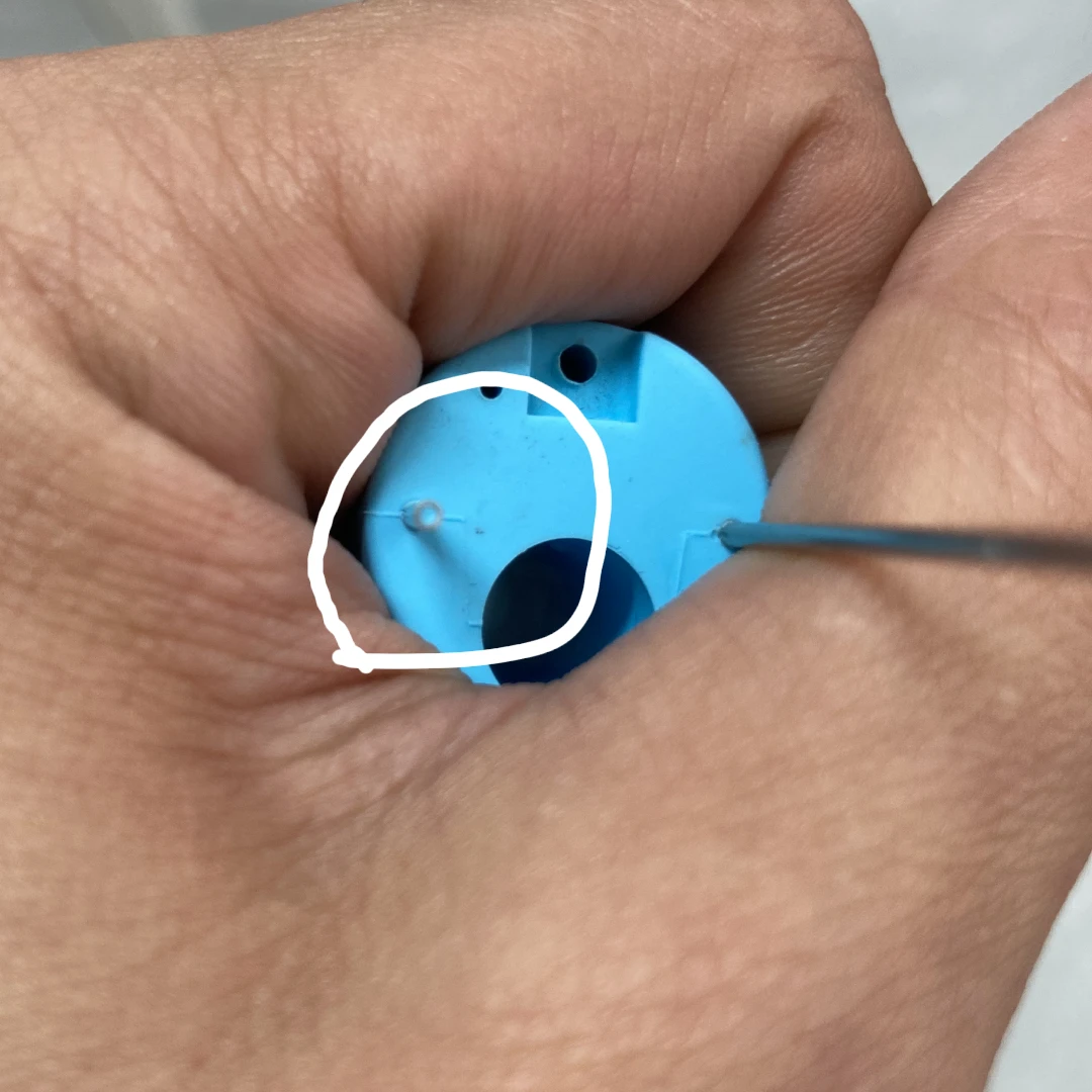
Needle Opening That Would Fill With Silicone
OVERMOLDING / TOOLING
A needle tube required silicone overmolding along its body. The open end was not blocked in the original design. During overmolding, silicone fills the needle bore. The part is unusable.
What we did
Machined a cap into the tooling to block the needle opening during overmolding. The cap is part of the mold, not the part. The needle bore stays clear. No change to your design was needed.
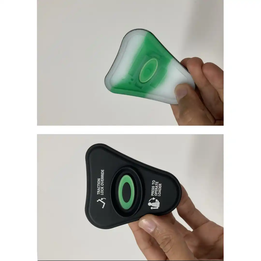
Two Materials, One Part
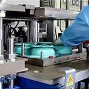
COMPRESSION MOLDING / MULTI-SHOT
A part requiring two silicone materials different colors or durometers in a single molded piece. Without a planned cavity sequence and gate location, one material bleeds into the other at the interface.
What we did
Defined fill order, gate location, and interface geometry for each material before tooling. For parts that also need fabric reinforcement or a substrate insert, separate tooling stages are planned from the start.
Design Resources and Next Steps
Once your design is validated, we define process and cost parameters and select the right manufacturing route.
- Color & Branding: Pantone Color Matching for Silicone Products to manage color accuracy.
- Manufacturing Fulfillment: See which production method will be used on your project.