A Complete Guide to Silicone Product Design
Silicone is one of the most versatile materials in modern manufacturing. It is flexible, durable, temperature-stable, and safe for food, medical, and skin-contact use. But getting the most from it depends on decisions made long before tooling: good silicone product design is what separates a part that molds cleanly and performs for years from one that flashes, tears, or leaks.
This guide walks through the design considerations that matter most, from part geometry and sealing to material and process selection. At Dabojin, we support clients across the full arc of silicone product development, from early concept and design review through tooling and production. This reflects how we actually approach a project with a customer.
How We Approach Silicone Product Development
A typical engagement moves through a few clear stages:
- Design: you (or our team, with you) define the geometry, durometer, seals, and features. This guide covers this stage in depth.
- DFM review: once the design is finished, our engineers run a Design-for-Manufacturability pass to catch shrinkage, flash, venting, and tolerance issues before steel is cut.
- Tooling and validation: we build the mold, run first articles, and verify dimensions and properties.
- Production: repeatable molding at your target volume.
Designing with the later stages in mind is the single biggest thing you can do to control cost and lead time. Our Design Validation Process.
1. Choose Durometer by Function First
Hardness, measured on the Shore A scale, is a design input. It changes sealing force, feel, tear resistance, how deep an undercut can be stripped from the mold, and how a flexure behaves.
| Shore A | Characteristics | Common Uses |
|---|---|---|
| 10-20 | Very soft, gel-like | Gel pads, damping grommets |
| 30 | Soft, compressible | Baby nipples, keypads |
| 40 | Medium-soft | Phone cases, baking mats, soft grips |
| 50-60 | Most common range | Kitchen tools, gaskets, O-rings |
| 70 | Firm and durable | Engine gaskets, firm feet |
| 80 | Very firm | Industrial rollers |
Softer silicone seals at lower force and strips deeper undercuts, but tears more easily and takes more compression set. Firmer silicone behaves more like plastic. It is less forgiving on ejection and needs more draft. Choose the softest durometer that still meets the structural and tear demands. Don't sacrifice flexibility unless you need to; very hard silicone loses stretch and is more prone to cracking.
2. Key Silicone Product Design Considerations
2.1 Parting Lines
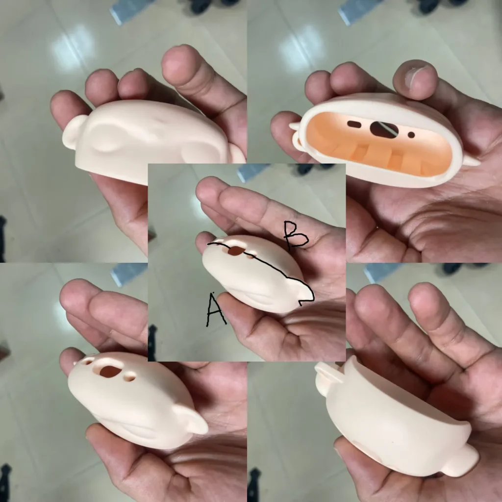
Imagine slicing your product in half. The line where it splits is the parting line, where the two mold halves (often labeled A and B) meet. A small witness line or flash always forms there.
Here is an illustration showing all sides of the product, along with a separate image labeled A and B. These labels represent the two halves of the mold that come together. The marked line indicates the parting line where the mold halves meet when filled with silicone.
- Keep it simple and straight. Straight lines are easiest to tool; avoid curves and angles that complicate the mold.
- Keep it off critical surfaces. The parting line should not cross sealing faces, cosmetic (Class-A) surfaces, or key structural features.
Note: parting lines usually aren't part of the initial design. They are determined during CNC programming. We always review parting-line options with the client, so the best thing you can do is leave clean, accessible surfaces where a line can sit without harm.
2.2 Draft Angles
A slight taper on surfaces parallel to the mold opening helps the part eject without damage.
- A safe default is 1-2° on vertical surfaces. Silicone often needs less draft than rigid plastics, and soft, smooth grades may release near-vertical.
- Add more draft for deeper draws, textured surfaces (roughly +1° per 0.025 mm of texture depth), and firmer durometers.
2.3 Radii and Fillets
- Sharp internal corners are tear-initiation sites and air traps. Round every one.
- Minimum internal radius 0.5 mm, and ideally ≥ 0.5× the local wall thickness.
- Carry a matching external radius so the wall stays uniform around the corner.
2.4 Undercuts
Unlike rigid plastics, silicone flexes, so moderate undercuts can often be stripped directly from a two-part mold. This eliminates the side-actions or manual inserts a plastic part would need and saves tooling cost.
- Keep undercuts shallow, rounded, and ramped (gentle lead-in/out) so the part stretches over them without tearing on ejection.
- Strippable depth scales with softness: soft grades (≤40A) tolerate larger undercuts; firm grades (≥60A) behave like plastic and may still need a side-action.
- Round every undercut edge. A sharp undercut edge tears during stripping.
2.5 Wall Thickness
- Maintain a uniform wall, typically 0.5-3 mm. Uniformity matters more than the exact number: uneven walls cure and shrink unevenly, causing sink, warp, voids, and dimensional drift.
- Core out thick masses. Replace a solid block with a shelled wall plus ribs.
- Transition thickness gradually (about a 3:1 taper), never an abrupt step.
2.6 Ribs, Bosses, Holes, and Text
- Ribs: thickness ≤ ~0.6× the adjoining wall to avoid sink; radius the base.
- Bosses: core the center of large bosses; keep surrounding wall uniform.
- Holes: through-holes beat blind holes; keep blind depth ≤ ~2× diameter.
- Text/logos: recessed (engraved) detail molds and wears better than raised; keep strokes ≥ 0.5 mm.
2.7 Avoid Unnecessary Complexity
Intricate features, sharp corners, and tiny protrusions invite sticking, defects, or special tooling. Ask whether every detail is necessary, and simplify where you can.
3. Sealing Design
Most silicone products seal something. A seal works by being compressed a controlled amount. Too little leaks; too much over-stresses the rubber and accelerates set.
| Seal Type | Target Compression (Squeeze) |
|---|---|
| Static O-ring | 15-30% of cross-section |
| Dynamic O-ring | 10-20% |
| Static face gasket / bead | 15-25% |
| Soft conformal gasket | Up to ~30-40% |
- O-ring glands: the groove must let the compressed ring spread. Design groove area ~10-25% larger than the ring so the gland fills to 75-90%, never 100% (an over-packed groove damages the ring). Round groove corners.
- Bead seals: for a gasket molded into a housing, use a raised half-round or trapezoidal bead (≈0.5-1.5 mm tall) to concentrate force into a line and seal at lower clamp load.
- Compression stops: add rigid standoffs that bottom out so assembly torque can't over-squeeze the seal. This is the single most common waterproofing fix.
- Compression set: leave useful deflection in reserve; don't run a seal at the top of its squeeze range.
- Waterproofing (IP-rated): use one continuous, captured gasket loop, radiused, with no parting line crossing it, paired with compression stops.
4. Functional Feature Design
- Keypads / membrane switches: a button is a thin collapsing dome web; web thickness and dome angle set the actuation force and tactile snap. Provide an air-relief path under each dome so trapped air doesn't slow the return.
- Valves (duckbill, umbrella, cross-slit, dome): cracking pressure is governed by lip/wall thickness, slit length, and durometer. Thinner, longer, softer opens at lower pressure. Round all root corners; these features cycle constantly.
- Living hinges: use a thin, generously radiused, uniform web with no sharp notch.
- Snap-fits: good for capture and alignment, weak for load-bearing (low stiffness). Round roots and lead-ins.
- Soft-touch grips: ~1.5-3 mm of silicone over a rigid backing feels right; thinner feels hard, thicker rolls. Terminate edges in a captured groove or thickened roll, never a thin feather.
5. Overmolding (Bonding Silicone to Plastic or Metal)
Silicone bonds to almost nothing on its own, so the interface is a design feature:
- Mechanical interlocks: through-holes, undercut channels, dovetails, or ribs in the substrate physically trap the cured silicone. This is the most reliable method and a smart backup even when using bonding chemistry.
- Self-bonding LSR or primers chemically bond to compatible, clean, properly textured substrates that tolerate the cure temperature.
- No feathered silicone edges at the bond perimeter. Start the silicone at a thickened, captured edge so it can't initiate a peel.
6. Choosing the Manufacturing Method
The process constrains your geometry, so pick it early.
| Method | Best For |
|---|---|
| Liquid Silicone Injection (LSR) | Smooth surfaces, complex shapes, high volume, precision |
| Compression Molding | Simple shapes, thick walls, lower volume |
| Overmolding | Bonding silicone over plastic or metal |
| Die Cutting | Flat gaskets or sheets |
| Extrusion | Tubing and continuous profiles |
| Dispersion Molding | Strength, conductivity, specialty functions |
What this means for your design: choose the right method, simplify features where possible, question whether every detail is needed, and consult engineers early. We are happy to advise on feasibility before anything is committed.
7. Material Selection
Silicone's headline properties: a service range from below −60°C to over +250°C (special grades to ~300°C), chemical and UV/ozone resistance, mechanical flexibility and durability, and excellent electrical insulation.
Types of Silicone
| Type | Application Example |
|---|---|
| General-purpose | Sealants, greases |
| High-temperature | Cookware, heaters |
| Water-clear | Cosmetic containers, optical adhesives |
| Medical-grade | Implants, diagnostic tools |
| RTV | On-site sealing and bonding, prototyping |
| HCR | Gaskets, molded parts |
| LSR | Precision injection molding |
| Platinum-cured | Cookware, biocompatible parts |
| Aluminum-cured | Cost-effective gaskets |
| Silicone resins | Heat-resistant coatings |
Match Type to Application
| Application | Recommended Silicone |
|---|---|
| Kitchenware | General-purpose, food-safe |
| Medical devices | Biocompatible (ISO 10993 / USP Class VI) |
| Aerospace | High-temperature resistant |
| Cosmetic | Water-clear |
| Seals / gaskets | HCR |
| Precision injection parts | LSR |
| Cost-sensitive | Aluminum-cured |
8. Surface, Texture, and Color
The part mirrors the mold finish, so specify it. Glossy silicone is grippy and shows flow and parting marks. A light texture hides witness lines, reduces the tacky/dust feel, and improves grip. For low-friction needs, design in texture, a coating (PTFE/parylene), or a self-lubricating grade. Silicone holds pigment stably; provide a target and we will handle the match (see also: Color and Branding: Pantone Color Matching).
9. Design for Manufacturability (DFM): After the Design Is Finished
Once your design is finalized, our engineers run a DFM review before tooling. This is where we tune the part for the realities of the mold:
- Shrinkage: silicone shrinks ~1.5-3% as it cures; the tool is cut oversized to compensate, so we lock the exact compound at this stage.
- Tolerances: we set realistic rubber tolerances and place critical dimensions in one mold half (fixed dimensions hold tighter than those crossing the parting line).
- Gating and venting: we position gates off cosmetic/sealing faces and add venting to prevent short fills.
Common Molding Challenges We Resolve in DFM
| Issue | Solution |
|---|---|
| Flash | Clean, flat, well-placed parting lines |
| Air traps | Avoid isolated thick areas; design for venting |
| Sink / warp | Uniform walls; core out thick sections |
| Tearing on ejection | Radius corners and undercuts; right durometer |
Designing with these in mind from the start makes the DFM pass fast and inexpensive.
Silicone Product Design and Development With Dabojin
You don't have to figure out silicone product design alone. If you have a concept, a sketch, or a rough CAD model, our team can help refine it into a manufacturable part: durometer selection, seal and feature design, draft and parting strategy, and material choice.
And if you go on to manufacture with us, that design work flows straight into silicone product development: we run the DFM review, build the tooling, validate first articles, and move into production. One continuous path from idea to finished product, with the same engineers throughout.
Have a project in mind? Talk to our team and we will help you get the design right the first time.
FAQ
Can silicone be molded onto plastic or metal?
Yes. This is called overmolding, using a mechanical interlock, a primer, or a self-bonding silicone.
What is the ideal wall thickness?
0.5-3 mm, kept as uniform as possible.
What hardness should I choose?
It depends on the application. Around 30 Shore A for baby products and soft grips, 70+ for industrial parts. Choose the softest durometer that meets your structural needs.
When do you do DFM?
After the design is finished. We review the finalized geometry for shrinkage, tolerances, flash, and venting before cutting any tooling.
See also:
- Color & Branding: Pantone Color Matching